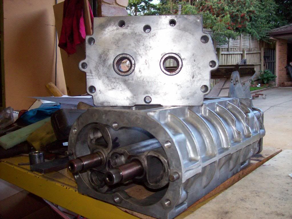
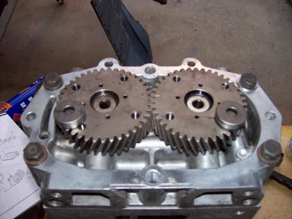
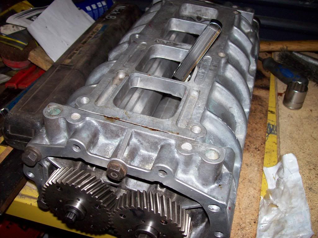
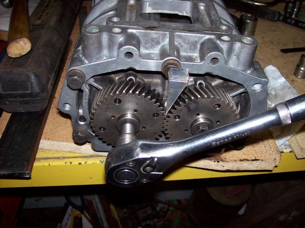
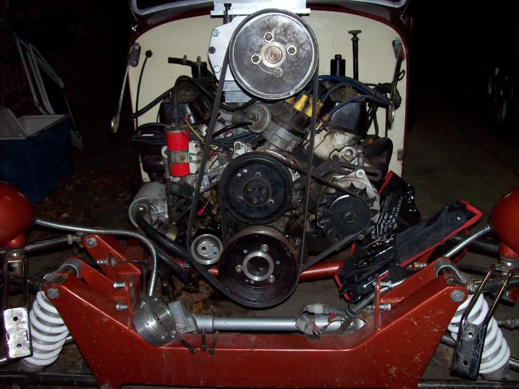
Just been trying to get over the embarasment that, yes, with the drive on this side of the blower it will go BACKWARDS!!!!!!!!

! I must thank you trackdodge for noticing this as I would have spent more time on it before I would have noticed. Will keep this one for when/if the blower is mounted the other way.
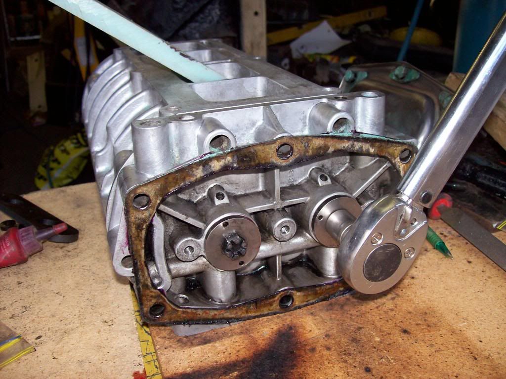
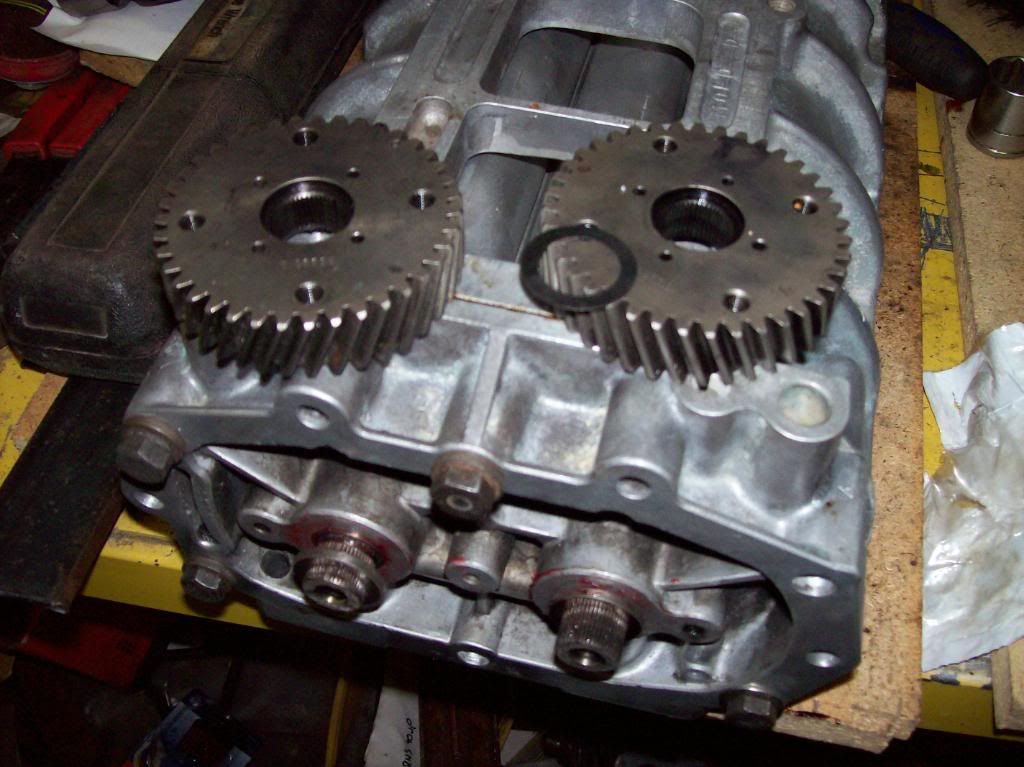
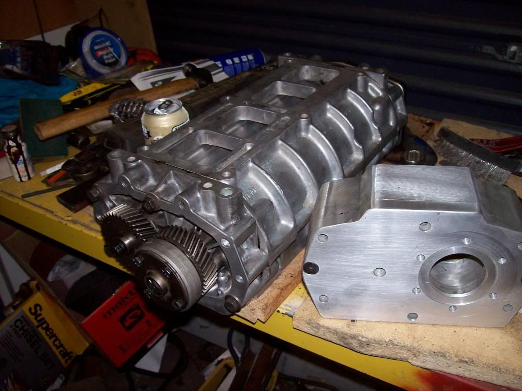
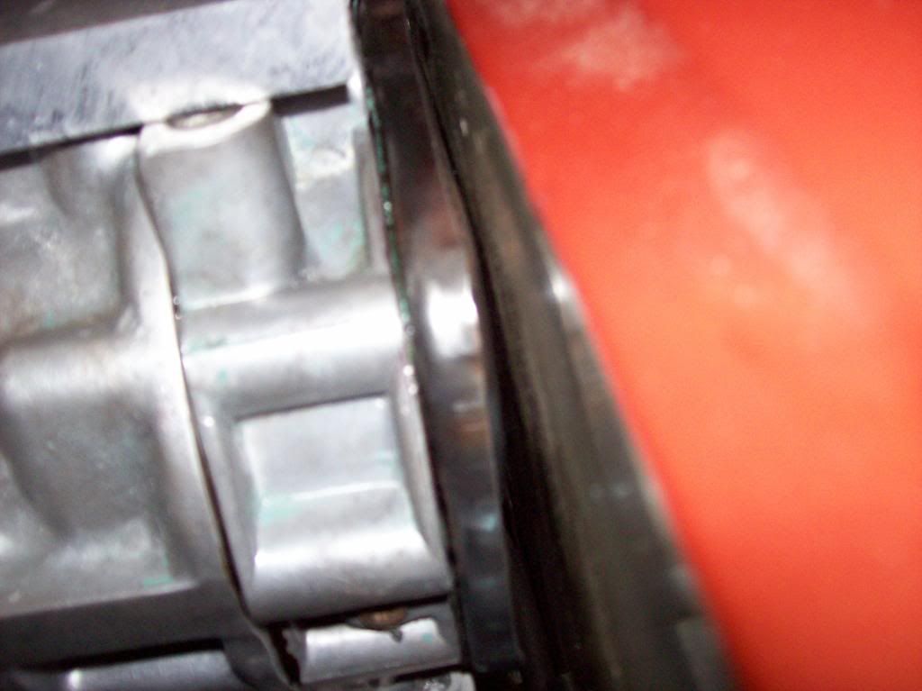
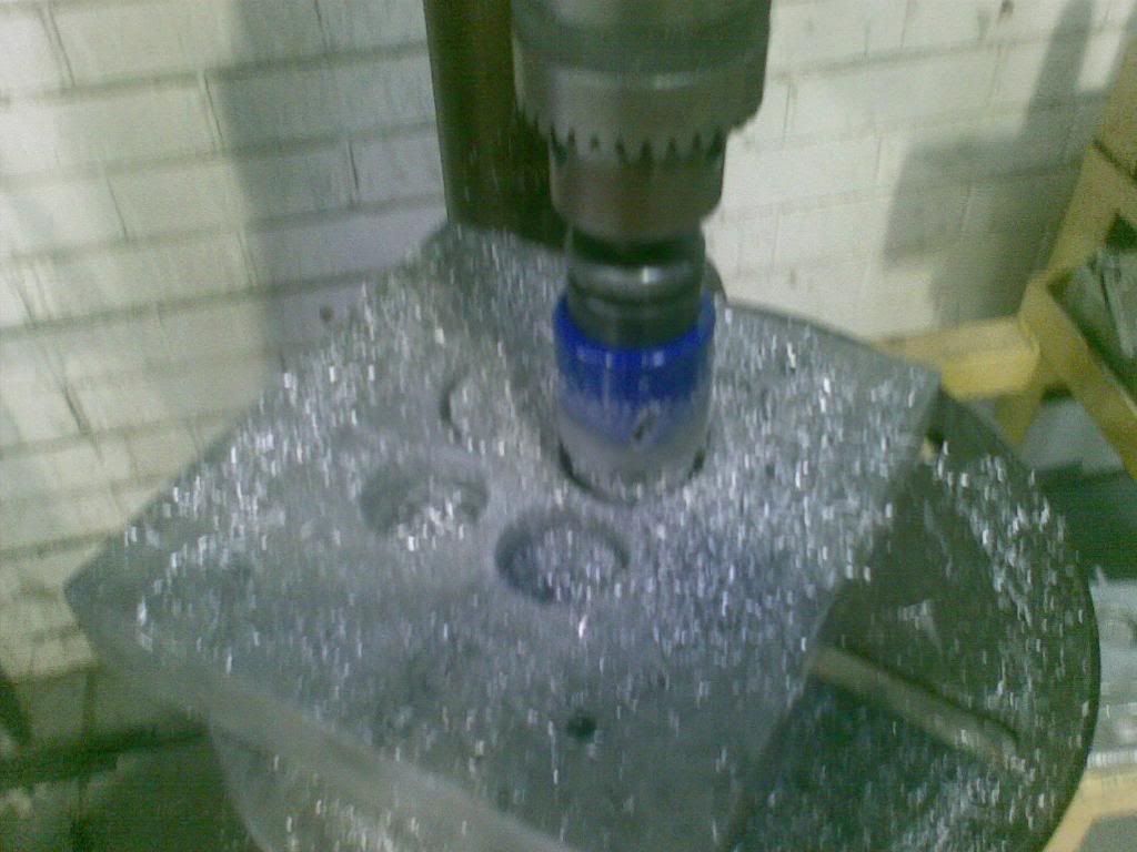
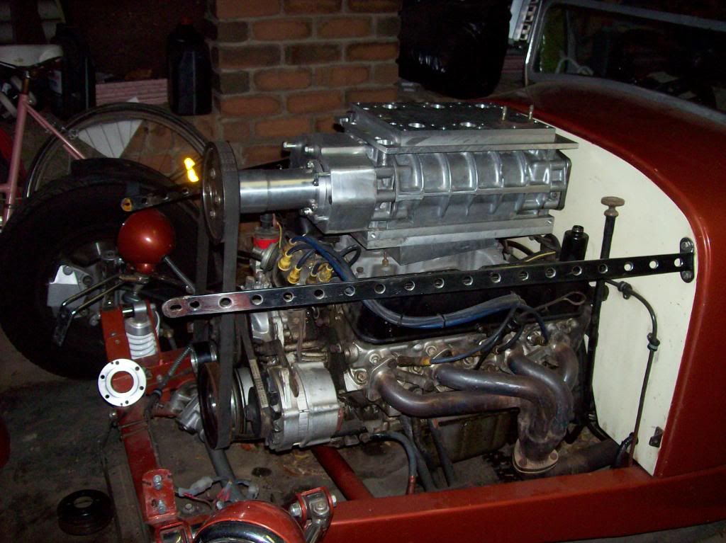
I am going to use a 6rib multi "V" belt from a falcon or commodore (want parts to be locally available). I can not have blow off valves and this type of belt will slip. The pulleys have been machined up from filled double "A" series pulleys.
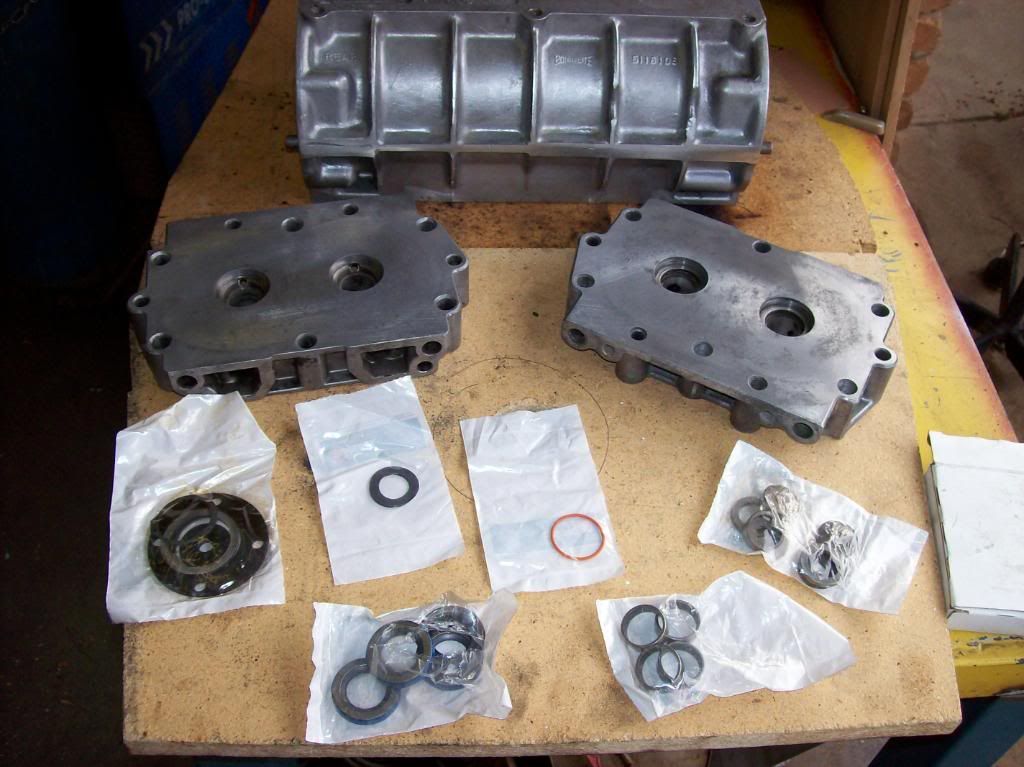
Cam and reground lifters arrived Friday, so now I can reassemble the engine. It has had the main and big end bearings replaced due to wear of the main thrust bearing surface. Fitted a centre main "strap" while the sump has been off and some sump mods to stop an oil leak.
Bates; settle mate this is a hotrod forum and "THEY" probably won't allow those other things

!
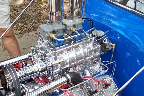
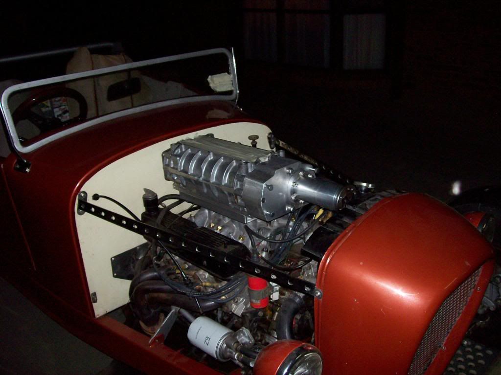
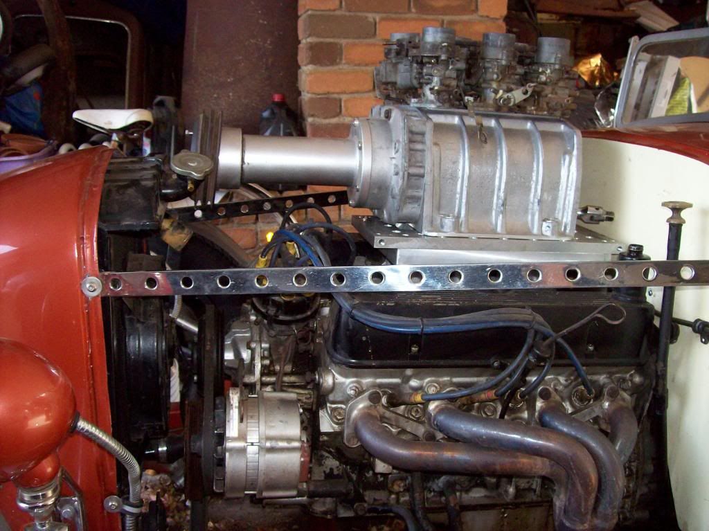
A few engine specs;
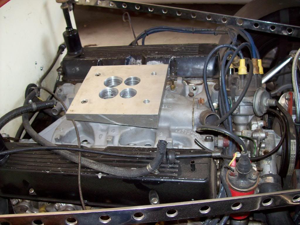
Ford Flathead Canadian 59a
239ci bored to 258ci
1.6" manley pro flow inlet valves, 1.5"manley pro flow exhaust valves
Isky 88cam, isky springs, hollow adjustable lifters. Being replaced by Crow blower grind.
Edelbrock heads and super dual inlet, being replaced by blower.
Ross forged pistons with deck relief.
Full oil filtering system
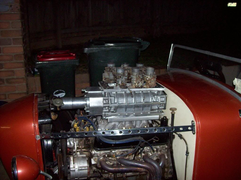
2x2bbl Marvel Chebler 10-3300 carburetors
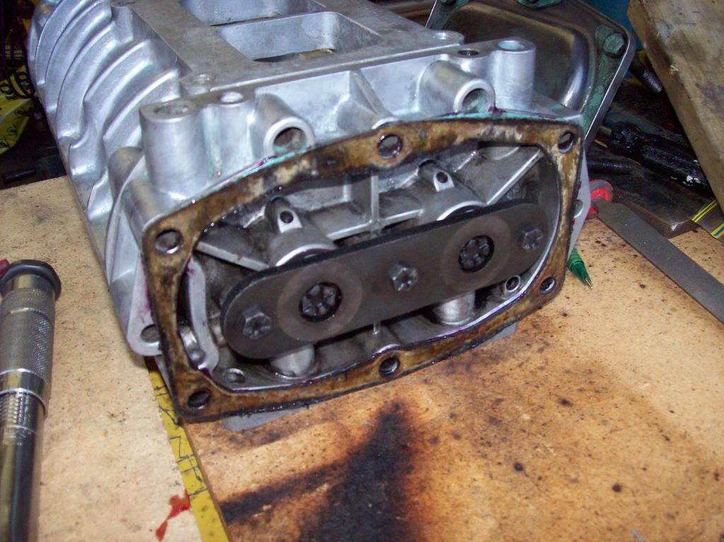
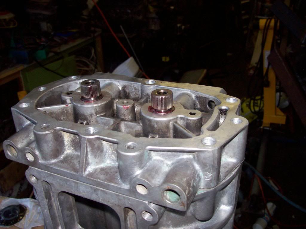
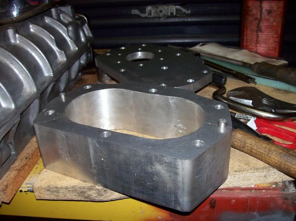
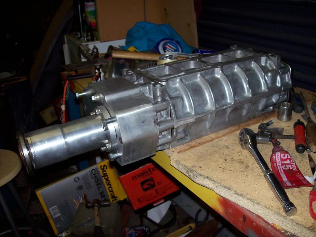
GMC 6V53 blower, looking at a target of 2 to 3psi boost
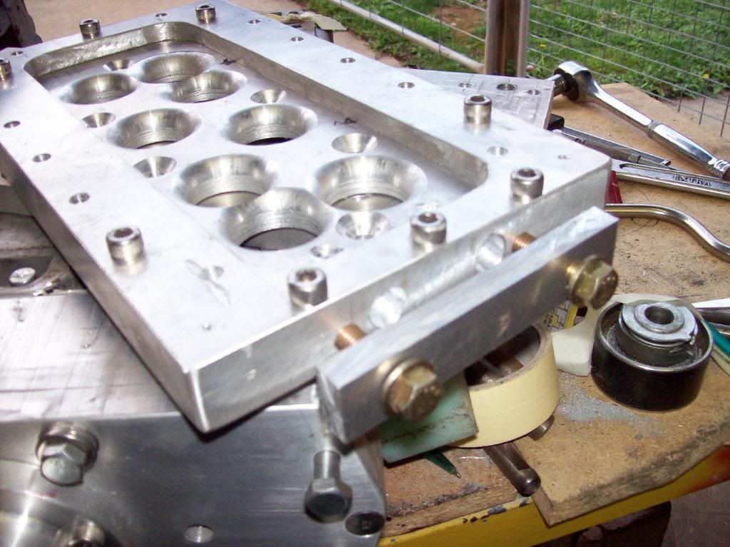
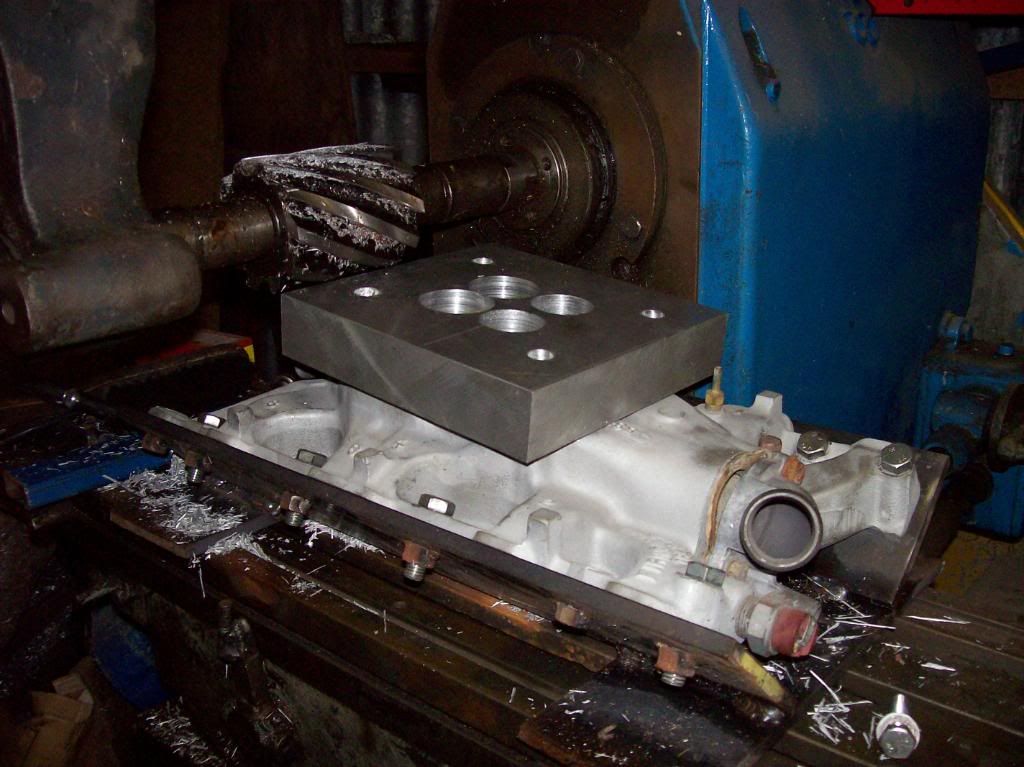
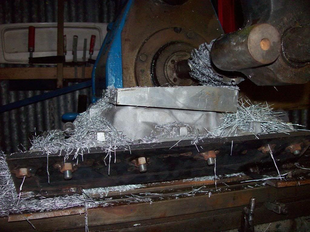
Intercooler, water cooled manifold and 1/4" phenolic resin manifold insulator.


![[img]http://a.imageshack.us/img706/8749/p1060364x.th.jpg[/img]](http://img706.imageshack.us/i/p1060364x.jpg/)